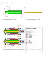
Select [Replay] to play again from beginning or [Adjust] to see adjusting the space between pen and paper or [Pen] to see solenoid lifting the pen.
Dark grey on the left side is the metal plunge with pen (not shown). Light grey on the right side is the plastic container for liquid ink.
The drawing is to scale.
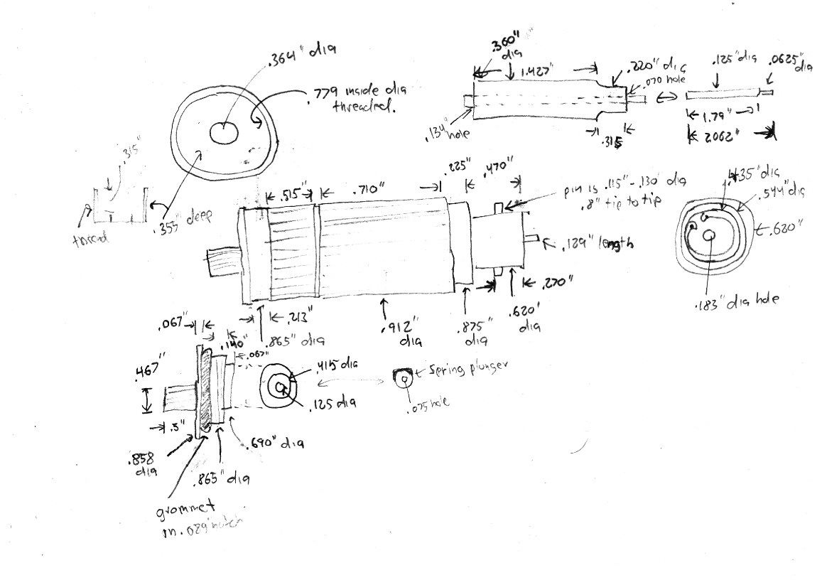
This document shows drawings based on dimensions from Herb Johnson's web site.
Please download it and see if you can provide any dimension of your pen holder. There seem to be a variety produced.
This is work in progress and I will post here further versions.
My email address is tom [AT] tomislavmikulic [DOT] com.
 Dimensions-01.doc [450 KB]
Select [R] for Replay or [P] for Pen.
Dimensions of the coil and coil compartment are calculated not meassured.
The drawing is to scale.
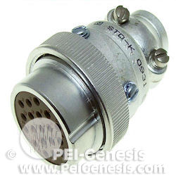
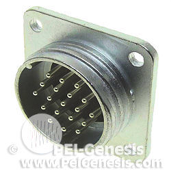
Found a site where the brand new 19 pin connectors can be purchased: PEI-Genesis.
They are very beautiful but rather pricey - about $150 - $120.
Very detailed technical specification is available on-line.
Click on the thumbs to check for yourself.
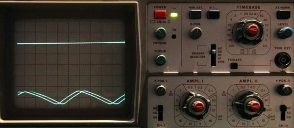
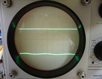
I found the DC outputs from power supply pretty clean except the -24V.
Hopefully it will not affect functioning of the plotter, cannot say yet because of other problems I have with some poor contacts.
This ripple comes from the PS unit with C2 and C3 capacitors of 500 MFD each.
The plotter with C2 and C3 of 750-1500 MFD each has significantly improved signal, i.e. much less rippling.
My plotter is powered by 115V/50Hz transformer plugged to 240V/50Hz mains.
Yes, I need a US round 2 prong power cable connector mating the one on the back plate of the plotter! Have a spare? Gimme a yell please.
Photo on the left shows the ripple on my plotter and David's on the right. Thank you David for the comparison.
Good point Herb! It's a good idea to show cap from other angles.
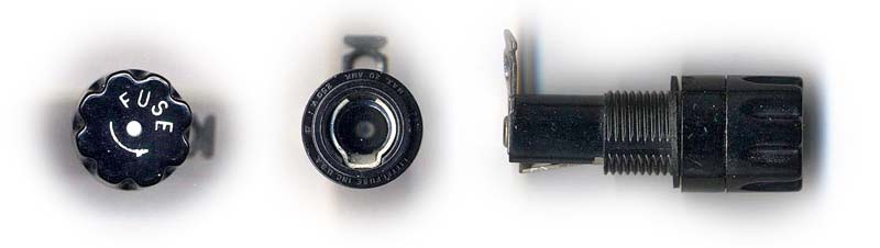
On the left side is the original one. On the right side is the modern one from a local parts store.
Note that the original is bayonet type. The standard 3AG fuse (2A, slo-blo) in photo is only a size guide.
This photo shows the actual item I bought.
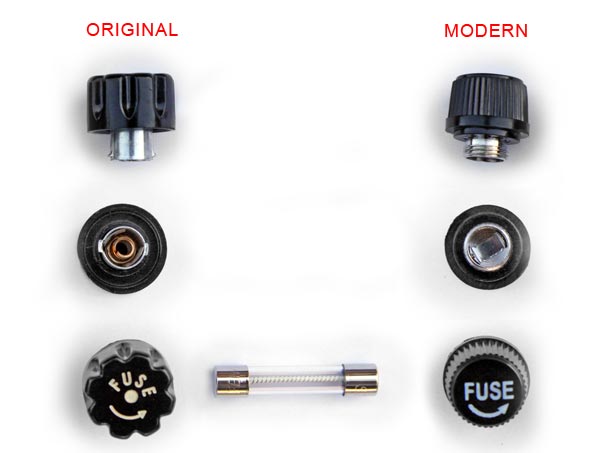
The 3AG fuse holder mounted on the back plate of the plotter is in nice condition except the bayonet cap was missing.
I bought locally a contemporary fuse holder but it wasn't good because cap is with a thread.
There are quite a few offered on eBay. I am glad I found the vintage one identical to the original.
It is NOS (New Old Stock - never used). It arrived in the mail a week later.
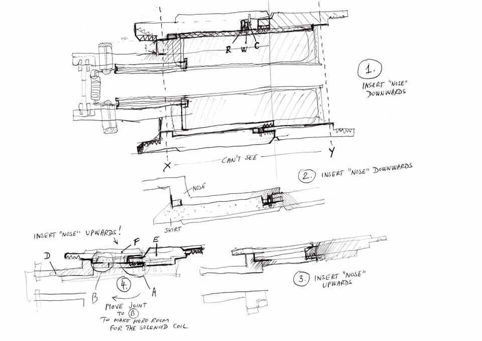
Potential concept. Before I start making a proper technical drawing with dimensions and in proportion I need to understand connection between each individual part. Since we don't have access to see the parts inside the pen holder I started thinking how would I put it together.
First I thought the lower part ("Nose") should be inserted through the lower ribbed cylinder ("Skirt") downwards and fixed there against the stoper ring (R) with a washer (W) and a C clip so that it cannot move back. The upper ribbed cylinder would be screwed into it. You can see this concept sketched in drawing 1. and 2.
Tried to put things together in the oposite direction. If Nose (D) is inserted through Skirt (F) upwards it can simply be fastened with the upper skirt (E). This turned to be a very simple solution and most likely this is how it is done. See pic 3. and 4. I will need to work out where to put the threaded joint to make most of the room for the solenoid coil.
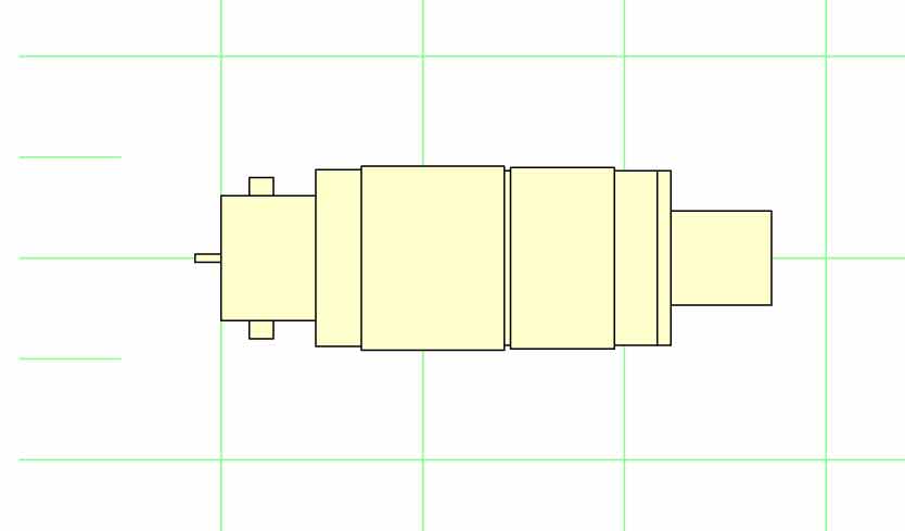
First drawing . I'll keep adding details to this basic drawing. When all parts are drawn I'll need to add dimensions.
Very useful links (checked and updated on DEC 20, 2012):
David Gesswein
http://www.pdp8online.com/563/563.shtml
Jeffrey S. Jonas
http://ferretronix.com/1627/
Herb Johnson
http://www.retrotechnology.com/restore/calcomp565.html
Gerold Pauler
http://pdp8.de/en/frames/set_calcomp.html
Instruction Manual for Calcomp plotter 565, searchable text:
http://www.dvq.com/docs/manuals/cc565_inst.pdf
Instruction Manual for Calcomp plotter 565
http://archive.computerhistory.org/resources/access/text/2009/09/102646345.05.01.acc.pdf
Video with sound of Philipp's plotter 565 working (YouTube)
http://www.youtube.com/watch?v=dSEvVxdJNIw
and some nice photos of his Calcomp 565 plotter .
IBM ploter 1627 Model 1 (Relabeled Calcomp 565)
http://www.ibm1130.net/functional/Plotter.html
Dr. E.H. Dooijes
http://www.science.uva.nl/museum/calcomp565.php